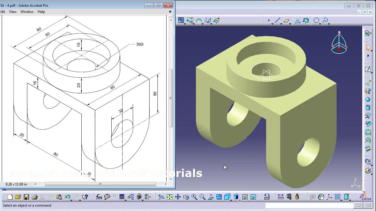
There is a square placed on the dimension in the text properties area its not in the tolerance menu. The bellow video is about how you can create a simple part using simple commands in CATIA V5 Part Design module.

I Need Drawing For Practice In Wireframe And Surface Design Grabcad Questions
Advanced Surface Design Version 5 Release 20 Revision 10 Prepared and produced by.

. Hope you found todays CATIA Tip in a Minute or Less to be useful if not just interesting. Then CATIA calls to Select a dimension or geometry as reference to line-upin the bottom left corner of the screen. Click the callout center.
CATIA to know the design intent. Create Text Below Drawing Dimensions Catia Macro. From drop down option of numerical properties you will get the dimension digit option.
Decimal inches and feet should be preferred because of the. The dimension will have a curve above the numerical display to indicate what the type is. CATIA V5R16 surface modeling Mouse Tutorial 2A To confirm that the size of the drawing is correct- Click Dimensions icon.
This tool is used in the design of various objects such as vehicles buildings components etc. You can split a body with a plane face or surface. CATIA geometrical modeler lets you complete highly complex mechanical products and parts with great accuracy from concept to detailing.
CATIA V5R16 Fundamentals Constraining the sketch Dimensional Constraints click the icon then select the elements Length Distance Angle RadiusDiameter Remark. October 29 2007 1051 PM in response to James Bishop Hello there In 2D drafting when a length dimension is created Right-click will give you an option of curvelinear. You can turn off the displaying of colors in the drawing if unselecting the icon on the bottom menu in drawing mode.
If you have some drawings I. Create Text Below Drawing Dimensions jagandeep Automotive OP 23 Jul 13 2124. Once you create and dimension the sketch in the part make sure it is shown.
See the attached image for more clarity. CATIA Tutorials Basic Advance and Surfacing tutorials Pdf Download. To create the dimensions continuously double-click the icon so that the icon is always on until you re-click it again Geometrical Constraints.
First column defines offset of the smallest dimension from the edge. On the icon is a dimension with a spy glass But beware you will loose the ability to see if the dimension is disconnected from 3D therefore I recommend you to turn it off only before drawing. Hello All I have to create text indicating number below each and every dimension for every view.
Advanced Surface Design Version 5 Release 20 Student Guide Revision 10 June 2011 ASCENT - Center for Technical Knowledge CATIA. For more questions or videos please check my YouTube Channel and also the CATIA video tutorial section from this blog. Click on the scale line of the drawing.
This tutorials includes an introduction of the main features in the 3D design software package Catia V5. Answered on 7 Feb 2013 0429 AM. Beside the basic tools of 3D design a number of exercises and examples point to different construction strategies in several applications.
It is a three dimensional modeling tool. Or go to the main menu Tools Positioning Line-up. It is not the purpose of this course to teach GDT but.
Angle refers to the relative orientation of lines on a plane or. There is a option in catia drafting called numerical properties. ADVANCED SURFACE DESIGN ASCENT Center for Technical Knowledge.
To that end the most comprehensive process coverage is available including high-quality surface and part design assembly creation mechanism motion 3D mock-up review and drawing generation. Remember that 1 254 mm. Advanced Surface Design student guide expands on the knowledge learned in the CATIA.
Check if the displayed dimension is 50mm. After you choose the material for you part you can very easy track your dimensions. If not we need to enlarge or shrink the drawing into the correct size.
Select all affected dimensions right click and select Line-Up option. From your tree select the top element name of the part right click and choose Proprieties. Dimensions for curves 122 Generative Dimensions.
It is similar in use to Autocad NX Formerly known as UG Pro-E. Introduction to Surface Design student guide by covering advanced curve and surface topics. Drawings are dimensioned in decimal feet.
Right click on tool bar and make sure tha tab is click on. There you can change your digit as per desired. Create a length dimension on a curve.
Drag to select the callout radius and click a point to end the selection. ASCENT Center for Technical Knowledge 1001 E. Settings dans latelier Drafting.
X 14inThe CATIA V5-6R2015. Creating a Detail View Detail View Profile In the Drawing window click Detail View in the Views toolbar Details sub-toolbar. Easy in adding subtracting etc numbers in decimal system.
The re-route dimension icon can be found at the picture. Flatness controls how flat a surface must be in order to meet the design requirements. And to do that you have several methods to display that.
Click to generate the detail view. CATIA V5-V6 CAD CAM Exercise module is intended for students or beginners who are willing to learn solid and surface design as well as NC machining. How do you split in Catia.
To reduce the time or you can think of this as a work around you can create a sketch in the part file to represent the mating geometry then show the sketch dimensions in the drawing view without creating a feature for it. To copy and paste the drawing into 3D space-. Right now I am doing it manually.
In CATIA we can re-route a dimension without deleting the dimension that was wrongly created. The Line-up dialog box appears. If we need to take this a step further within Tools Options Mechanical Design Drafting Dimension setting By default create dimensions on circles to Edge will take care of this in a more permanent fashion.
If u dont have that. 10m edited 10m. CATIA is a French designed Computer Aided Design CAD tool.
The sample exercises provided in this module is designed to provide self learning guideline for users with easy step by step instructions. How to display the weight mass center of gravity and surface in CATIA V5.
I Need Drawing For Practice In Wireframe And Surface Design Grabcad Questions

I Need Drawing For Practice In Wireframe And Surface Design Grabcad Questions

Pin On Catia V5 Video Tutorials
Catia Surface Design Exercises For Beginners 2 Catia Surface Design Tutorial Youtube
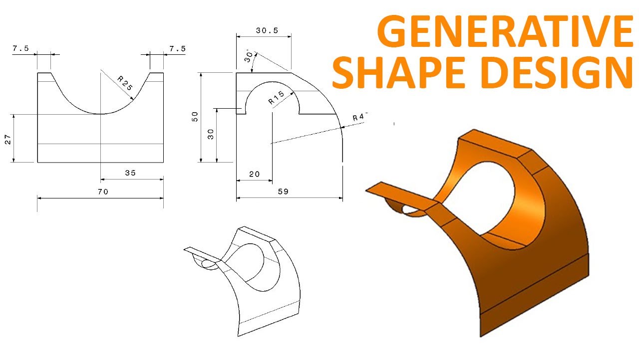
Generative Shape Design 1 Catia V5 Beginner Tutorial How To Use Extrude And Split Youtube

How To Create A Mechanical Part Using Catia Part Design Surface Design Mechanical Design Mechanical Engineering Design
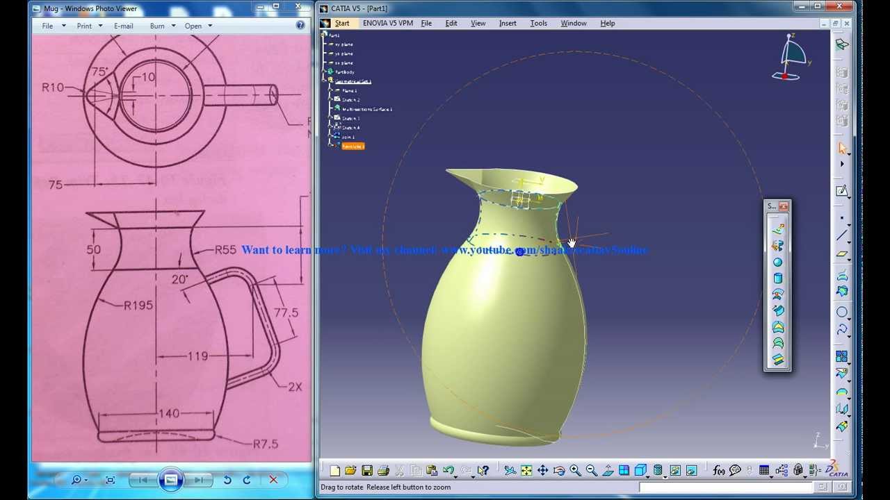
Catia V5 Tutorials Wireframe And Surface Design Rebuild A Mug Part 2 Youtube

Catia Simple Surface Design For Beginners Youtube
0 comments
Post a Comment